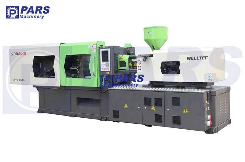
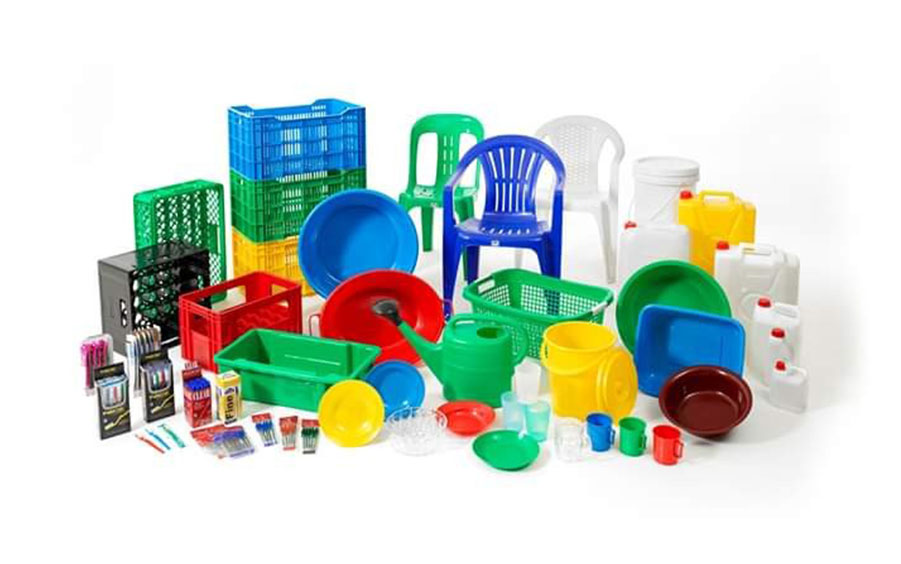
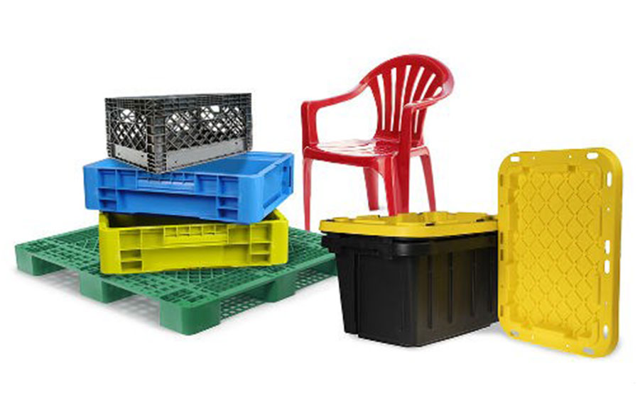
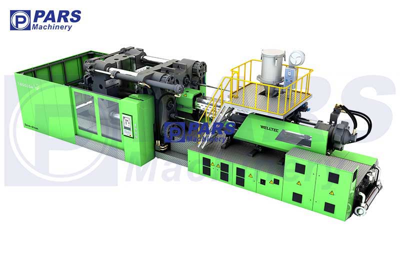
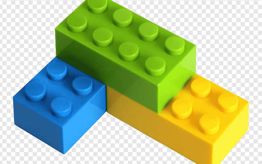
Plastic injection molding machine is one of the most common methods of converting plastic from raw to used goods.The plastic injection process is usually used for thermoplastic materials that may be melted, deformed and cooled sequentially. Plastic injection components are a feature of almost all functional manufacturing products in the modern world, from automotive products to food packaging. This versatile process allows us to produce high-quality, simple or complex parts fully automatically and at high speed with materials that have changed the face of manufacturing technology over the last 50 years.
Background of injection machine
To understand the engineering and operation of modern plastic injection molding machines, let’s first take a look at the process’s not-so-distant origins. The first plastic injection machines were based on pressure casting technology used to process products, with patents filed in the 1870s in the United States specifically for celluloid processing. Further major industrial developments did not occur until the 1920s, when a series of manual injection machines were developed in Germany for processing thermoplastic materials. A simple lever arrangement was used to close a two-piece mold. Molten plastic was then injected into the mold to produce the molded part. As an inherently low-pressure process, its use was limited. Pneumatic cylinders were added to the injection molding machine design to close the mold, although little improvement was achieved. Hydraulic systems were first used in plastic injection molding machines in the late 1930s as a wider range of materials became available, although injection molding machine design was still largely associated with die casting technology.
The extensive development of plastic injection molding machine design into the machines we know today did not occur in Germany until the 1950s. Earlier plastic injection machines were based on a simple piston arrangement to push the material into the mold, although these machines soon became inadequate as the materials became more advanced and the processing needs became more complex. The main problem with the simple piston arrangement was that no melt mixing or homogenization could be easily transferred to the thermoplastic material. This was exacerbated by the poor heat transfer properties of a polymeric material. One of the most important advances in machine design to overcome this problem, which is still applied today in modern processing equipment, was the introduction of the injection barrel of a submerged spiral screw arrangement. This injection machine was subsequently known as the “reciprocating screw” plastic injection machine.
Injection molding machine cycle
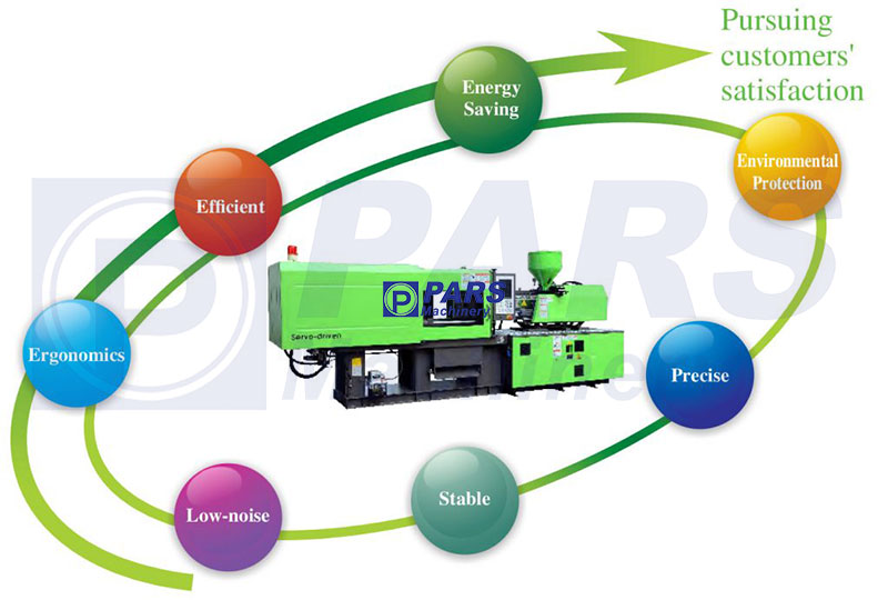
Today’s modern process has developed significantly to the point where fully automatic, closed-loop, microprocessor-controlled injection molding machines are the “norm”, although in principle injection molding is still a relatively simple process. Thermoplastic injection molding requires the transfer of polymer materials in the form of powder or granules from a feed hopper to a heated barrel. In the barrel, the thermoplastic melts and is then injected into the mold by some kind of piston arrangement. The mold is closed under pressure in a sheet arrangement and maintained at a temperature well below the melting point of the thermoplastic. The molten thermoplastic rapidly solidifies within the mold, allowing the part to be removed after a predetermined period of cooling time. The initial stages of the injection molding process with a plastic injection machine are as follows:
Closing the mold and clamp of the plastic injection moulding machine
The mold is closed in the plate arrangement and is closed using the force necessary to hold the mold closed during the plastic injection cycle, thus preventing the plastic from leaking onto the mold surface. Today’s plastic injection machines range from about 15 to 4,000 metric tons of clamping force (150 to 4,000 kN).
There are many open/close systems and injection molding tools available, although there are usually two general types. Direct hydraulic locking is a system in which the moving injection machine plate is driven by a hydraulic piston arrangement that also provides the force necessary to hold the mold closed during the injection operation. Alternatively, smaller auxiliary pistons may be used to perform the primary movement of the plate, and a mechanical blocking arrangement to transmit the locking pressure from a pressure booster at the rear of the device, which moves only a few millimeters, to the device. to be
The second type of general clamp arrangement is called toggle lock. In this case, a mechanical ratchet device, attached to the back of the movable plate, is actuated by a relatively small hydraulic cylinder, providing movement of the plate as well as the clamping force when the pawl joint is finally locked like a strap arrangement. he does.
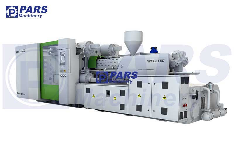
Injection molding machine
At this stage of the injection machine cycle, the helical injection screw is in the “behind the screw” position and has a load of molten thermoplastic in front of the screw tip approximately equal to or slightly greater than the amount of molten material required. To fill the mold cavity, injection molding screws are usually designed with a length-to-diameter ratio in the region of 15:1 to 20:1 and a back-to-front compression ratio of about 2:1 to 4:1 to enable gradual thermoplastic compression. . During material melting, a check valve is installed in front of the screw, allowing material to pass in front of the tip of the screw during metering (dosing of material), but not allowing material to flow over the screw during injection. come back The bolt is located inside the barrel, which has a hardened wear-resistant inner surface.
Typically, ceramic resistance heaters are installed around the barrel wall, these heaters are mainly used to heat the thermoplastic material in the barrel to the required processing temperature and compensate for the heat loss through the barrel wall, because during processing most of the heat is lost. The need for processing is created through the cut created by the screw. Thermocouple pockets are machined deep into the barrel wall to provide a reasonable indication of melt temperature. Therefore, the heat input can be controlled with a proportional integral and derivative (PID) system. The (non-rotating) screw is driven forward under hydraulic pressure to discharge the thermoplastic material from the injection tube through the injection nozzle, which forms an interface between the barrel and the mold, and into the molding tool itself.
Keeping pressure and cooling
The screw is held in the forward position for a certain period of time, usually with a molten “cushion” of thermoplastic material in front of the tip of the screw, so that a “holding” pressure may be maintained on the solidifying material inside the mold. It allows compensating materials to enter the mold as the mold piece solidifies and shrinks. Hold pressure may be initiated in one of three ways: with a specified time in seconds from the start of the injection filling phase; with the position of the screw at the end of the injection stroke. or by increasing the hydraulic pressure measured by a pressure transducer in the mold itself or in the injection hydraulic system.
As the material solidifies to the point where the holding pressure no longer affects the mold packing, the holding pressure may drop to zero, which helps reduce residual stresses in the resulting molding. After the pressure holding phase is over, the mold must be kept closed for a specified period of cooling time. This time allows the heat from the mold to dissipate into the mold tool so that the mold temperature reaches a level where the mold can be removed from the mold without excessive distortion or shrinkage. This usually requires the molding to reach a temperature below the thermoplastic rubber transition temperature or Tg (glass transition temperature). Depending on the type of plastic, this can be in a few degrees or more than one temperature range. Mold temperature control is usually incorporated into the tool through channels for pressurized water flow. Depending on the material being processed, the type of part and the amount of production required, the mold may be connected to a cooling or water heating unit.
Dosing or measuring injection materials
During the cooling phase, the barrel is charged with material for the next molding cycle. The injection auger rotates and due to its helical nature, material in granule or powder form is drawn through the hopper feed to the rear end of the barrel. The throat connecting the hopper to the injection barrel is usually water-cooled to prevent premature melting and subsequent bridging of the material that interferes with feeding. The speed of rotation of the screw is usually set in revolutions per minute, which is measured using a proximity switch on the back of the screw. The screw rotation may be set as a constant speed during the measurement or as several speed steps.
This material is gradually moved forward on the lines of the screw and gradually melts so that when it reaches the front of the screw tip it must be completely molten and homogeneous. Molten material transferred in front of the tip gradually pushes the bolt back until it reaches the required shot size. Increased shear is introduced into the material by restricting the backward movement of the screw, this is done by restricting the flow of hydraulic fluid exiting the injection cylinder. This pressure is referred to as “back pressure” and helps to homogenize the material and reduce the possibility of unmelted material being transferred to the front of the screw.
Once the cooling phase is complete, the mold is opened and the part is removed. This is usually done with ejector pins in the tool that are coupled to a hydraulic actuator via an ejector plate or by an air ejector valve on the die tool plate. Moldings may fall freely into a collection box or on a conveyor belt, or may be separated by an automatic robot. In this second case, the molding cycle is fully automatic. In semi-automatic mode, the operator may intervene manually at this stage of the cycle to remove the mold. Once the mold is removed from the mold tool, the complete molding cycle can be repeated.
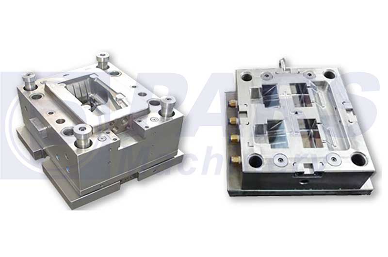
Mold design of injection molding machine
Mold design of the injection machine itself is a very diverse and complex issue. However, it is useful to understand the basic features of designing and making simple injection molding tools.
The mold is simply composed of two halves, usually called the movable half (core) and the fixed half (cavity). Starting from the injection side, a locating ring is installed behind the rear backing plate, positioning and centering the mold in the fixed plate. A spruce bush can be seen through the locating ring. The sprue bushing is profiled with a radius to match the nozzle of the injection unit so that material can be transferred directly from the injection unit into the mold cavity. In the case of a single die (cavity) die, the sprue may be fed directly into the part, in the case of a multi-die, the sprue feeds on a runner system machined into the tool face that acts as a transfer system to The device works.
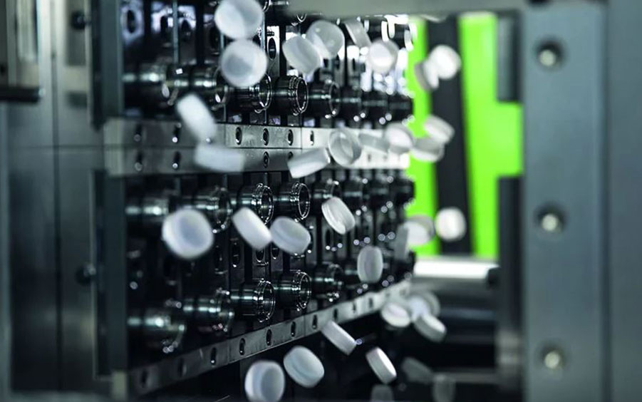
PET preform injection machine
Cavity for molten material Hot or hot runner systems may be incorporated into the fixed half of the mold so that the runner and sprue feed system is constantly molten and thus not ejected at the end of the cycle. Instead, the molten material remaining in the hot runner system after injection of one component forms part of the next shot. Different types of gates can be used to connect the runner system to the mold cavities. Preferably the gates are as small as possible to minimize the potential “witness” mark on the part. It can be seen that a sprue and a cavity form the shape of the component, these may be machined directly into the solid steel or aluminum plates, or separately fabricated as inserts which may subsequently be machined into the core holder plates. and install the hole. In this particular example, hardened pins are used to eject the part from the mold, these pins are fixed in a rear ejector plate which is connected to a hydraulic actuator behind the moving plate. A profiled ejector pin on the back of the sprue bush ensures separation of the sprue from the sprue bush when the mold is opened and helps eject the runner system. Cooling channels are machined into the core and cavity plates to remove process heat from the tool. The complete tool is assembled with a system of spacer blocks, supports and back plates so that it can be bolted directly to the machine plates and is completely rigid and able to withstand injection forces.
injection molding machine selection criteria
Choosing a plastic injection molding machine can be very difficult, especially for a wide range of component types. It is always wise to discuss the general specifications of the machine with the machine suppliers. However, there are rough guidelines to allow estimating the type and size of the injection machine
injection
The mold of the plastic injection machine must be accessible in the clamping area. This is usually determined by the tie rod spacing on the injection molding machine that limits mold attachment and removal. Some machines have retractable tie rods to aid in die changing. The available clamping punch must be able to accommodate the mold height or mold depth and the opening punch required to eject the plastic part. For free fall throwing, the daylight between the plates must be greater than the height of the mold plus twice the depth of the piece to be thrown. It should be noted that if, for example, the component is removed by a robot, this dimension must be significantly greater to allow access for the removal head. It’s always wise to allow plenty of room to maneuver for the car’s subsequent flexibility.
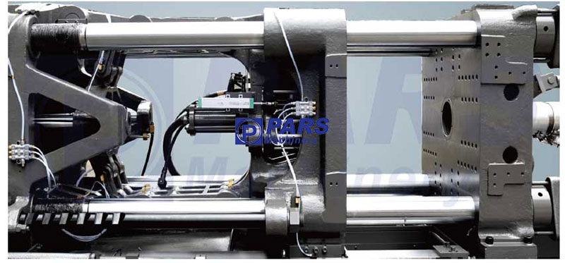
Clamping unit of injection molding machine
The clamping unit must be able to provide sufficient locking force to hold the mold closed during the injection step, otherwise the mold will separate and the molten material will flash over the mold gap line. As a rule of thumb, parts with thin wall sections and deep draw depths require approximately 3-4 tons per square inch or 0.5-0.6 tons per square centimeter, and parts with thick wall sections and shallow draw depths require approximately 2 tons per square inch. need square inches. or 0.3 tons/cm2. To calculate the required locking force for a specific component, this value must be multiplied by the projected area of the component to obtain an overall value in tons. The projected area of a component is considered to be only one side of the mold, perpendicular to the injection unit as it is oriented in the mold. For example, a simple box enclosure with a 3 mm wall section and a top surface of 120 cm2 requires a minimum locking force of 120 x 0.3 = 36 tons.
Injection unit
The injection unit must be able to provide the shot weight of the component (including sprue and runner system). The total weight of the shot should not exceed 90% of the injection capacity of the machine. Injection capacity is usually stated in grams of polystyrene at a specific gravity of 1.03 g/cm x 3. If another material is to be processed, the injection unit shot weight must be recalculated using the specific gravity of that particular material.
Since screw sizing or recovery must be done before cooling time has elapsed and the mold is opened, the injection unit (screw size) must be sized to allow this to occur. If recovery does not occur during the cooling period, the overall cycle time is unnecessarily increased.
The maximum possible temperature on the barrel should be high enough to melt the type of plastic being processed.
If certain abrasive materials such as glass fiber filled polyamide (nylon) are to be processed, the barrel and screw must be specially treated. Also, the screw geometry must be correct for processing specific materials, although general-purpose designs are available for processing a wide range of commodity thermoplastics.
Molding quality
Thermoplastic molds may have many defects as a result of poor mold design, however, proper control of the injection molding process usually plays a major role in achieving a good quality component. The main quality defects of the part may be as follows.
Weld lines
Weld lines are formed when two or more flow fronts of the cooling melt meet inside the mold. This can be recognized in the mold as a hairline feature and occurs where the melt flow splits around an obstruction in the tool, such as a bass pin, and rejoins on the other side. Weld lines locally reduce the mechanical properties of the material at that point and care should be taken to position the valves to minimize weld lines. If they are unavoidable, they should be placed in areas of least impact. Melt flow software packages help a lot in this field for complex moldings. Changing process conditions such as increasing melt temperature, mold temperature or injection speed may improve the situation but may cause other problems.
shrinkage
Shrinkage occurs as the thermoplastic cools in the mold. At the molecular level, polymer chains are loosening (recoiling) and aligning themselves with neighboring chains. Increased shrinkage occurs with highly crystalline plastics (such as polybutylene terephthalate, PBT) due to the formation of denser crystal structures. Sink marks may occur on plastic parts in areas of thicker cross-section, such as the joints between the sidewall and base, where the plastic cools more slowly. Higher mold temperatures allow the plastic to shrink more due to increased molecular energy and subsequent recoil. Higher packing pressures may be compensated, as shrinkage can be removed with new melt (assuming the gate is still live).
Distortion and molding in tension
Stress distortion and molding may occur in molded components due to molecular chain orientation. As the polymer is placed along the channels or small sections, the molecular chains are aligned and stretched. As the polymer cools, the molecules try to relax into their preferred helical state. Since the cooling process is generally fast, the extended molecular chains are frozen in the untwisted state. After molding, the molecular chains still try to push back and the component may distort as a result, especially in the case of semi-flexible polymers such as polyethylene. With stiffer polymers, distortion may not occur, however, residual stress in the plastic leads to a reduction in important material properties such as impact strength.
Buy injection molding machine
Plastic injection machines can have many different capabilities according to customer needs. Based on this, we recommend that you click on the contact link and contact the sales experts of the company to get technical advice regarding the purchase of plastic injection machines and price inquiries.
Click on the link below to see the video of how the plastic injection machine works and the mechanism:
Watch the video of how the plastic injection machine works
“Dear ones, you can see all kinds of plastic injection machines (injection molding) and inflatable plastic machines (blomolding injection) on the Pars inflatable plastic machines website and contact us for guidance on buying a plastic injection machine.”
I like that the website provides a comprehensive FAQ section, addressing common questions and concerns.
I’ve had success in selling niche items through the platform, reaching a targeted audience interested in my products.